
12 Jul 2016
POSTED BY - Coal India
INTRODUCTION
Deposits of splittable sandstone exist in India and state of Rajasthan is leading in production. Splittable sandstone is used in construction as roofing stones as well as for beams, pillars, arches, wall facing etc.The compressive strength of splittable sandstone varies from 35 MPa to 110 MPa in the Jodhpur area where field experiments were carried out. The sizes of the extracted blocks were generally 1.2m width, 3m-4m length and thickness upto the nearest cleavage plane. The blocks were then further split manually with the help of chisel and hammer to make sized form of saleable product. During the process of splitting and sizing manually about 75% valuable sandstone was converted into waste. Thus, improved extraction technique is required to reduce the waste generation at sandstone quarries. In small sandstone quarries, where cutting machine cannot be used, controlled fracture growth without damage in desired direction by blasting appears to be the only attractive technique to enhance the recovery1–2.
In the splittable sandstone, any unwanted crack converts it into small pieces as waste or low value saleable product. Hence, it is important that waste generation in splittable sandstone be reduced by improved blasting technique during the extraction of stone blocks. Keeping all these aspects in mind, field tests were devised in sandstone quarry for development and growth of macro cracks in the
desired direction only while preventing the unwanted generation of micro cracks in the extracted block and remaining rock. On the basis of field scale tests, the analysis was attempted on these lines in the present research work.
LTERATURE REVIEW
During blasting, explosive energy transmitted to the rock besides doing useful work of fragmentation and displacement, may cause damage in the remaining rock in the form of unwanted macro to micro level cracks. Considerable efforts have been made to study the rock damages due to blasting and also to minimize damage for last many years in conventional blasting3–6. But very scanty work has been carried out in dimensional stone damage assessment. The damages are to be reduced in dimensional stone extraction blasting, where small amount of explosive energy is used to separate rock or to split the separated blocks.
Unwanted damages are required to be minimized in conventional rock excavation in several situations such as pit wall blasting, tunnel and underground chambers excavations. Blast damaged roof and walls of an underground chamber in rock require an excessive amount of support and reinforcement. The over break and damage to remaining rock can lead to safety problems due to rock falls and additional costs incurred in supporting the strata. Further, the controlled blasting is useful in long-term stability of the finished tunnel. The well planned controlled blasting can reduce the cost of excavation in addition to stability7–9.
The extent of damage is not solely a function of blast ground vibration but also related to other site-specific parameters such as rock strength, and geological
structure features7. The jointing in rocks creates imbalance in the distribution of explosive energy causing blast damage. The presence of joints also affects the attenuation of the stress wave. Further, the presence of clay material in joints, its swelling potential and thickness contribute to poor rock mass quality, thus, resulting in excessive over break and under break6. As a result, in dimensional stones, presence of joints reduces the recovery of saleable product.
All controlled blasting techniques such as cushion blasting, pre-splitting, smooth blasting have one common objective, namely, to distribute the energy delivered in rock mass by explosive detonation in a better way so as to control crushing and fracturing. In pre-splitting, a row of holes was drilled along the final wall excavation line and holes were loaded with light charge of explosives. Detonating cord quarrying technique in extraction for dimension stone can be considered as extreme case of pre-splitting with a total absence of random radial cracks and a controlled displacement of separated rock mass. Blasting techniques such as cushion blasting, pre-splitting, smooth blasting are used to control the unwanted cracks in the remaining rock in conventional blasting. But these techniques develop micro level cracks which are not desirable in dimensional stone extraction. Thus, an improved and cost effective technique is required to control damages in dimensional stones.
TECHNIQUES FOR DAMAGE ASSESSMENT
Various techniques such as, physico-mechanical properties, rock quality designation (RQD) of core samples, thin section study under petrological microscope, computerized x-ray tomography and measurement of p -wave velocity have been developed for detection of blast induced damages6, 9–14. Amongst these, ultrasonic p-wave velocity determination technique is the most proven and very reliable for damage detection at macro as well as micro crack generation level15.
Fundamental concept of p-wave measurement is that, the fracturing and micro cracking in a finite region occurs due to blasting in rock mass, which causes the decrease of p-wave velocity in the region5,16. The p-wave velocity forundamaged rock mass after blasting remains same as that before blasting. Thus, for determination of damages in blasted block, ultrasonic p-wave velocity measurement serves as a good indicator for characterization of the damage due to crack formation.
p-wave Velocity
For assessing the quality of rock, p-wave velocity is measured with ultrasonic equipment (ultrasonic concrete tester) which is non-destructive type and works on the principle of sound wave. It has two transducers, which are placed across the rock specimen for measuring p-wave. One transducer emits pulse, which is received by other
transducer and the time taken determines the p-wave velocity. The distance, which the pulses travel in the rock, is also measured with the help of scale to calculate the pulse velocity.
In general higher the velocity, higher the quality of rock or less damage in the rock in the form of micro level to macro level fracturing. It can be theoretically proved that the velocity of a pulse of longitudinal ultrasonic vibrations in an elastic solid can be given by the equation :
|
V |
= |
E (1− ν) |
|
|
|
|
|
|||
|
ρ (1 + ν )(1 − |
2ν ) |
|||
|
|
|
where V is p-wave velocity, km/s; E, modulus of elasticity, MPa; ρ, density, g/cm3; ν the Poisson\'s ratio.
EXPERIMENTAL DESIGN AND
METHODOLOGY
The tests were designed in uniform type of splittable sandstone quarries for assessment of damages due to blasting. The site selected was Jodhpur sandstone area. A sandstone formation was uniform type and it was easy to quantify damages. The tests designed were :
Design of Experiments
Various experiments were devised for determination of damages in extracted blocks and remaining rock. The details of design and selected parameters of experiments are described here.
Blast Designed Parameters
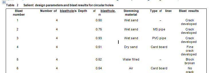
The designed parameters of circular and notched blasthole with air/water/sand as stemming material, with/without liners, burden and spacing are given in Table1.
Blasthole Liners
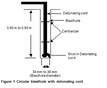
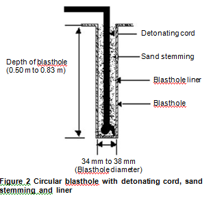
Three types of slitted liner devices were selected and used for the experimental work. These devices were M S pipe, polyvinylchloride (PVC) pipe, and cardboard (paper tube) types of slitted liners were selected. The position of circular holes without liner, circular holes with stemming and liners and notched holes with liners are given in Figures1 to 3.
Blasthole Shape
Circular and notched blastholes were selected to carry out the experiments. Circular hole is the traditional practice and easy to drill, while notched holes control damages and increase hole spacing, hence, these were selected for experimental purposes.
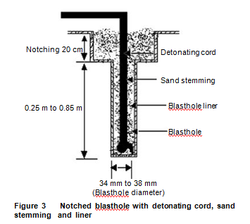
Notching of Blasthole
Notching is an effective means of raising the stress concentration around the blasthole, ensuring that crack should initiate at notched locations. Thus, notches are to be made along the line of cut/split direction. The notched blasthole required fewer holes and less explosive was needed to achieve the same or better results in comparison to those obtained with conventional circular hole blasting with detonating cord. The hole spacing can be increased by 25% as compared with circular hole17. Further, by notching, the risk of damage to the rock can be reduced. The notched hole is an effective technique to control the fracture in desired direction and also to control unwanted damages.
Collection of Sample Block of Sandstone
Sandstone formation selected was uniform and only one cubic block of 300 mm size before blast was collected and subsequently cores were obtained from that in the laboratory for determination of p-wave velocity and geo-mechanical properties. Sample blocks were extracted by drilling the holes at close interval in horizontal and
vertical directions and separation was carried out by feather and wedge. These extracted blocks were brought to the sandstone cutter. A perpendicular cut was provided in the sample block to detect visually the crack generation pattern, in order to precisely locate the coring points in the laboratory subsequently. In the laboratory, cores of
42 mm diameter were obtained from the sample block at a distance of 20 mm, 80 mm and 140 mm to determine the p-wave velocity and related geo-mechanical properties.
BLASTING PROCEDURE
Circular Blasthole Tests
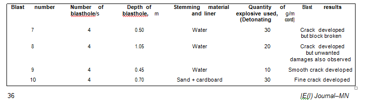
Blasting with detonating cord of 30g/m quantity was tried in circular holes. The blastholes were either left unstemmed or were stemmed full column with water or sand. Detonating cord was used as an explosive with a knot. The knot was tied at the end of the detonating cord to keep the cord straight in the blasthole. Thereafter, initiation of blast was carried out. The patterns of the circular blastholes are illustrated in Figures 1 and 2. The blast parameters for circular holes with air/sand/water as stemming material and with or without liners and visible results are given in Table 2.
Notched Blasthole Tests
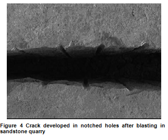
Blasting with detonating cord of 10g/m, 20g/m and 30g/m quantity with water filled holes were tried in notched holes. The results with 10g/m in water filled notched hole are shown in Figure 4. The notching of blastholes were not carried out along full length of the blasthole but only upto a depth of 20 cm to control the direction of
this was in all the samples and thus, it was not taken into considerations in assessment of damages.
RESULTS AND DISCUSSIONS
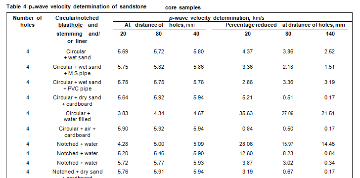
The p-wave velocity of core samples of fresh (undamaged) sandstone block measured was 5.95 km/s and which was taken as standard value (S/V) of undamaged sandstone block (Figure 5). The results of the p-wave velocity and percentage change in p-wave velocity for ten sandstone quarry blasts under study are tabulated in Table 4. The Table 4 shows that the p-wave in the core before blasting of fresh sandstone was always higher than after blasting. Similarly p-wave velocity in the cores after blasting was lowered near the blasthole and it was increased as the distance increases from blasthole. This finding is in line
with earlier findings16 and is due to generation of cracks after blasting. The results of p-wave velocity obtained on the basis of circular and notched holes with air or water or sand as stemming material, and, with various liners are discussed as here :In water filled circular blastholes damages observed were on higher side. Thus, the reduction in p-wave velocity were more as shown in Figure 5. Hence, water stemming is harmful in dimensional sandstone. Reduction in p-wave velocity with sand stemmed blasthole is less as compared to water filled/stemmed holes but there was very less reduction in p-wave with air filled/stemming. The reason being the dissipation of explosive energy in air filled blastholes.


Reduction in p-wave velocity in circular hole with cardboard liner was less as compared to M.S. pipe and PVC pipe liners as shown in Figure 5. The reason being the cardboard (paper tube) liners are having voids which provide the attenuation to stress wave in the region of blasthole to be protected from damage. Cardboard liner also provides the cushion to accommodate the gases by compression during the process of blasting. Further, transportation and handling of the cardboard is comparatively easy and bear no extra cost. It can be slitted at site and no pre-arrangements are required. It can be cut at site of use and given appropriate shape. However, for MS pipe and PVC pipe slitting is a specialized work and it is carried out much prior to its use. Thus, slitted cardboard liners were experimented and found more suited to control the damages.
The experiments in sandstone quarry were also carried out with water filled notched blastholes spaced at 300 mm which revealed a significant reduction in p-wave velocity with 30g/m and 20g/m detonating cord but very less reduction in p-wave with 10g/m detonating cord as given in Table 4 and Figure 6. Experiment with sand stemmed and cardboard liner notched blastholes spaced at 300 mm were also carried out and revealed a negligible reduction in p-wave indicating no damages in the extracted blocks. Nevertheless, reduction in p-wave velocity was less in notched holes as compared to circular holes.
The values of p-wave observed are shown in Figures 5 and 6. The reduction in p-wave velocity was observed in circular hole without liner but with notched hole and by providing the liners, macro crack developed in desired direction and other damages were minimized.
CONCLUSIONS
pipe, PVC pipe and card board liners in the blastholes.
4. In sandstone quarry blasting using 10 g/m detonating cord at 0.30 m spacing in notched holes even without liner and with water filling no damage was observed at (0.02 m distance) just adjoining the blasthole. This was indicated by 3.86% reduction in p-wave velocity.
REFERENCES
2.S Bhandari and S S Rathore. \'Development of Macrocrack by Blasting While Protecting Damages to Remaining Rock.\' Proceedings of 7th Int. Symp. on Rock Fragmentation by Blasting,Beijing, China, August 11-15, 2002, p 176.
3. M Paventi, Y Lizotte, M Scoble and B Mohanty. \'Measuring Rock Mass Damage in Drifting.\' Proceedings of 5thInt. Symp. RockFragmentation by Blasting, FRAGBLAST-5, Montreal, Canada,August 25-29, 1996, p 131.
4. P Rai. \'Investigation of Firing Patterns on Fragmentation in an Indian Opencast Limestone Mine.\' International Journal QuarryMaster, February 2004, p 33.
5. J C Zhang and C Chang. \'On Damage Mechanism of Micro Crack Zone in Rock Blasting and its Measurements.\' Proceeding of 6th Int. Symp. Rock Fragmentation by Blasting, FRAGBLAST-6, The South African Inst. of Mining and Metall., Johannesburg, August 8-10, 1999, p 358. S P Singh. \'Blast Control Damage in Jointed Rock Mass
7.T R Yu and S Vongpaisal. \'New Blast Damage Criteria for Underground Blasting.\' CIM Bulletin, March 1996, p 139.
8. M Jen. \'Micro and Macro Crack Growth as a Result of Blasting.\'Proceedings of 7th Int. Symp. Rock Fragmentation by Blasting,FRAGBLAST-7, Beizing China, August 11-15, 2002, p 155.
9. P A Rustan. \'Micro-Sequential Contour Blasting-Theoretical and Empirical Approaches.\' Proc. 5th Int. Symp. Rock Fragmentation by Blasting-FRAGBLAST-5, Montreal, Canada, August 25-29,1996, p 157.
10. D Darwin. \'Summary Statement for NSF Workshop on Rock Fracture, Report of Workshop on Assessment of Experimental Techniques Applicable to Rock Fracture.\' National Science